Functional Safety Suite 7.0
User’s Guide
3 Projects
The project organizes all data related to a problem. Therefore the first action after starting Functional Safety Suite is either opening an existing project or creating a new one. Only one project can be open at a time.
A project that has not been saved after the latest modification, is marked with an asterisk ‘*’ in the window title.
3.1 Packages
Models are organized in packages. This concept has been introduced in order to simplify handling of files and to create some kind of information hiding in a similar manner as modern programming languages do. Each package consists of one library and optionally some models.
There is always one global package. The global package has the same name as the project and is located in the project directory, i. e. there is one .lib or .gbes file with the name of the project in the project directory, and all model files in the project directory are models of the global package. When creating a new project, the global library is created.
There might be any number of local packages. Each local package is located in an immediate sub-directory of the project directory. The name of a local package is given by its directory name. The library of the local package has the same name as the package. In other words, whenever a sub-directory of the project directory contains a .lib or .gbes file with the same name as the sub-directory, it is regarded as a package.
A model has access to the library and the models of its own package and the global package. A model of the global package has access to its own package only, accordingly.
In general, you should keep the global package as empty as possible, i. e. create most data in local packages. In particular, you should create a separate local package for each hazard or safety function you want to analyze. Only those models and generic basic events, that need to be referred by models of different packages should be contained in the global package.
A new package is created by File – Create new Package. You will be asked for the name of the new package. A sub-directory with the given name will be created in the project directory, and the local library file will be created.
3.2 Models
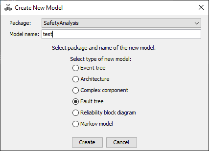
Functional Safety Suite supports models of the following types:
-
• Event Trees
-
• Architecture Diagrams
-
• Complex Components
-
• Fault Trees
-
• Reliability Block Diagrams
-
• Markov Models
A new model is created by File – Create new Model. The “Create New Model Dialog” will open, where you can select the package the new model shall belong to, and the name and type of the new model.
All model files found in a package directory will be loaded when opening a project.
3.3 Files
The following files are created and handled within a project:
-
• One project (.prj) file per project.
-
• At least one architecture symbol library (.sym) file per project.
-
• One generic basic event library (.lib or .gbes) file per package.
-
• Optionally one or multiple event tree (.etf) files per package.
-
• Optionally one or multiple architecture (.arch) files per package.
-
• Optionally one or multiple complex component (.cmp) files per package.
-
• Optionally one or multiple fault tree (.ftl) files per package.
-
• Optionally one or multiple reliability block diagram (.rbd) files per package.
-
• Optionally one or multiple Markov model (.mdg) files per package.
All files are text files in XML syntax. Therefore they can be read and their information can be interpreted and even changed manually (if someone considers this useful). XML schemes (.xsd) are available for all files.
In addition some evaluation results, intermediate results and graphics can be exported to files. Those files are described together with the related export command, see section 11.7.
Reports can be created in Office Open XML Document format (.docx), as used by Microsoft Office. 2
2 Please note that Libre Office or Open Office might not correctly work with the report files, unfortunately.
3.3.1 Project Files
The project properties as entered and shown in the project properties dialog are stored in the .prj file. The directory containing the project file is the project directory, and also contains the files of the global package.
3.3.2 Architecture Symbol Library Files
The graphic objects used to display component parts in architectures are stored in at least one symbol library file. A default symbol library file is shipped with Functional Safety Suite and located in the installation directory. Whenever a project is created, a copy of the default standard symbol file is created in the project directory.
You can create additional symbol files, in order to store your own symbols, created with the architecture symbol editor (see section 6.7). They will be located in the project directory as well. You can copy these files to other projects in order to re-use your symbols.
3.3.3 Generic Basic Event Library Files
The library file of the global package must have the name of the project. The library file of a local package must have the name of the package directory, extended by .lib or .gbes. 3 The library file only contains
generic basic event data. The generic basic events contained in the library don’t need to be actually used in the project. Each generic basic event data set includes the name and all parameters necessary to calculate the probabilistic values.
3.3.4 Model files
Each model has a name, that must be unique within the package. The name of the model is the same as its file name.
The complex component data is stored in one text file in XML format containing the following information:
-
• The component’s description as indicated in the properties window.
-
• The component’s maximum lifetime, test and repair times, evaluation mode and interval.
-
• Complete information of all component events.
Complex component file names must be extended by .cmp.
The event tree data is stored in one text file in XML format containing the following information:
-
• The event tree’s description as indicated in the properties window.
-
• Information of all conditions including the names of the cases, so that their referred generic basic events can be found when loading.
-
• The generic damages used in this event tree, including name, description and severity.
-
• Complete information of all crotchs including the structure of the event tree.
Event tree file names must be extended by .etf.
The architecture data is stored in one text file in XML format containing the following information:
-
• The architecture’s description as indicated in the properties window.
-
• The architecture components and the component parts each architecture component consists of.
-
• The name of the component part symbol to be used for each component part.
-
• Optionally the name of the generic basic event representing the failure mode of each component part.
-
• The nets connecting the architecture components.
Architecture file names must be extended by .arch.
The fault tree data is stored in one text file in XML format containing the following information:
-
• The fault tree’s description as indicated in the properties window.
-
• Some presentation related parameters.
-
• The mode how to convert branches to Markov models.
-
• The evaluation mode, algorithm and interval (in case of transient evaluation).
-
• Complete information of all gates including the structure of the fault tree.
-
• Names of the basic events so that their referred generic basic events can be found when loading.
-
• Optional suffixes and modifiers of the basic events (see section 7.3).
Fault tree file names must be extended by .ftl.
The data of reliability block diagrams is identical to the data of fault trees, and therefore the same file structure is used. The only difference is the extension .rbd.
The Markov model data is stored in one text file in XML format containing the following information:
-
• The diagram’s description as indicated in the properties window.
-
• Some presentation related parameters.
-
• Whether and how the model shall be pre-processed before evaluation.
-
• The evaluation mode and interval.
-
• Complete information of all states including the structure of the Markov model.
-
• Names of the edges so that their referred generic basic events can be found when loading.
-
• Optional modifiers of the edges (see section 9.3).
Markov model file names must be extended by .mdg.
3.3.5 Model Files not belonging to the Project
If you want a certain model to be excluded from the project, but not delete it completely, you can remove it by File – Remove active Model. This will unload the model and add _ignore to its file extension.
You can add an existing model, whose file is extended by _ignore, to any package by File – Add existing Model.
Of course you can also add, rename or delete files using a file system tool, such as Windows Explorer, but you shouldn’t do this while Functional Safety Suite is running in order to avoid inconsistencies.
3.4 The Project Properties Dialog
In the project properties dialog all options relating to all models of the project can be set. This information is stored in the project file in the project directory (extension .prj).
Note: There are many more parameters that can be set for each particular model and will be stored in each model’s file, therefore. These parameters are described in the related model’s sections later in this manual.
3.4.1 General tab
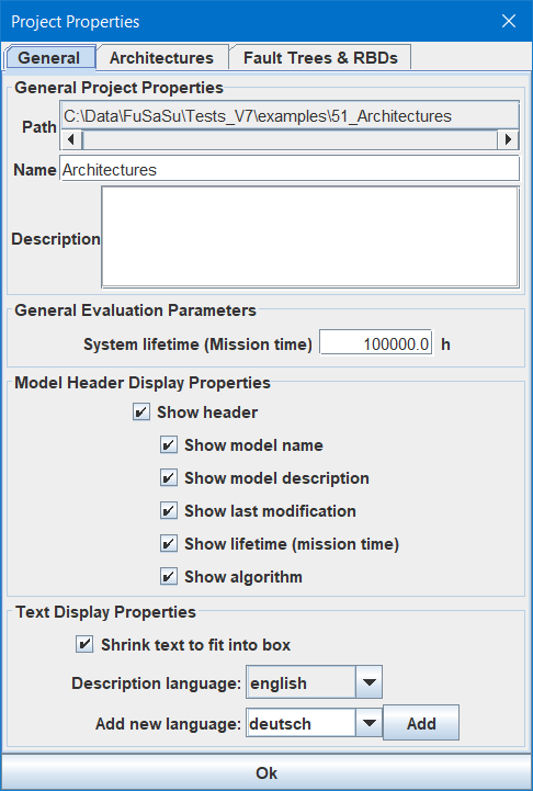
3.4.1.1 General Project Properties
Path: The path to the project directory.
Name: A user defined identifier of the project. The name is displayed in the title of the Functional Safety Suite window.
Description: An optional description of the project.
3.4.1.2 General Evaluation Parameters
System lifetime (Mission time): The system life time (in some literature called “mission time”) in hours. It is used to determine the unreliabilities (occurrence probabilities) F(T) and occurrence numbers N(T) as well as to calculate some values for some generic basic event models (see section 4) and complex components (see section 10). It is also used for Monte Carlo simulation of fault trees, see section 7.6.2.
3.4.1.3 Model Header Display Properties
Select whether to show a header in the graphics or not. Select which values shall be shown in the header.
3.4.1.4 Text Display Properties
Select ‘Shrink text to fit into box’ if you want the text size to be adjusted so that the text fits into the event boxes of fault trees or reliability block diagrams.
From version 6.0 on, all descriptions can be entered in multiple languages:
-
• project model descriptions
-
• architecture component descriptions
-
• architecture component part descriptions
-
• complex component failure mode descriptions
-
• generic basic event descriptions
-
• fault tree gate descriptions
-
• Markov model state descriptions
-
• event tree condition descriptions
-
• event tree generic damage descriptions
The active language is selected by the field Description language. The list contains all languages already defined for this project. Only the descriptions in the active language will be shown and can be modified, descriptions in other languages are kept in the background and will not be modified.
In order to add another language, select a language out of the list in Add new language and press Add. If the list of predefined languages doesn’t contain the language of interest, you can type any other name. There is no difference between predefined languages and any other name, the list is only intended to guarantee that you use the same name for the same language in different project, so that you can import models or packages from other projects without problems.
If you didn’t enter a description for the active language yet, the description of the first language will be shown instead.
3.4.2 Architectures tab
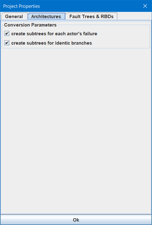
Select in which way a fault tree derived from the architecture is automatically split into sub-trees. See section 6.6.4 for more information.
3.4.3 Fault Trees & RBDs tab
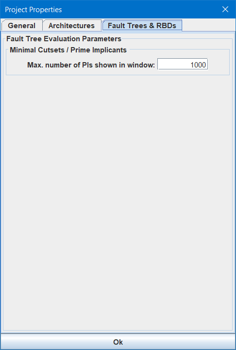
3.4.3.1 Minimal Cutsets / Prime Implicants
Max. number of PIs shown in window: This parameter is related to the Minimal Cutsets / Prime Implicants window, see section 11.6.3. In case of large fault trees with thousands of prime implicants, it might take quite some time to pop up the window. Since you’ll usually be interested in the most critical prime implicants only, putting all prime implicants in the window is a waste of time and memory. In case of an export to a CSV file, all prime implicants will be exported.